Attaching additional peripherals
The gateways has a number of headers that allow connecting LEDs, a reset button, or a temperature sensor. This page provides some details on how to connect these components.LEDs
The LEDS header has 5 pins. Pin 1 is connected to VDD (3.3V/5V), the other 4 pins can each drive a LED. Each LED should be connected via a current-limiting series resistor between VDD and one of the other 4 pins. The anode of the LED should be on the VDD side and the cathode toward the output for the specific LED. The resistor may be placed on either side of the LED, whatever is easiest in the design.An additional 2 LEDs may be connected to pin 2 and 3 of the GPIO header. The GPIO header doesn't provide VDD, so the anode side of these LEDs must also be connected to pin 1 of the LEDS header. A configuration with the maximum number of LEDs would then be hooked up like this:

You can choose which color LED to use depending on the function you are planning to assign to the LED. I'm using the default assignments (that's how they came to be the defaults), and chose orange for LED A (Flame), green for LED B (Transmit) and LED C (Override), and red for LED D (Maintenance).
Different color LEDs have different forward voltage drops and will require different resistors to get the same current to pass through them. On the other hand, some LEDs may appear brighter than others when using the same current. I'm happy with 330 Ω for my orange LED, 470 Ω for the green ones, and 680 Ω for the red one. You may want to get a bunch of different resistor values (between 220 Ω and 1 kΩ should normally suffice) and experiment with them on the work bench to find the best fit for your LEDs.
Reset button
It can be useful at times to be able to reset the gateway. This is accomplished by pulling the MCLR pin of the PIC low for a short while. A momentary switch can be hooked up to the RST header for this purpose. The RST header has 2 pins: pin 1 (near the R) is connected to ground and pin 2 (near the T) is connected to the MCLR pin of the PIC. Simply connect one of the two wires from the switch to one pin of the RST header, and the other wire to the other pin. Which one way around is not important. Just make sure you have a momentary switch, i.e. one that only makes a connection as long as you push it. A switch that can stay in the "on" position may continuously reset the PIC, preventing it from running its program.Temperature sensor
A DS18S20 or DS18B20 temperature sensor can be connected to the gateway to measure the outside temperature. The sensor has 3 leads: GND, DQ, and VDD. GND is available at pin 1 of the GPIO header, DQ should be connected to pin 2 of the GPIO header. VDD should be connected to 3.3V/5V (VDD), which is available at pin 1 of the LEDS header. However, putting both VDD and GND in a long cable that even goes outside feels a bit risky to me. A short-circuit between those two would completely disable the gateway, and with it any communication between the thermostat and the boiler. So I suggest to use pin 3 of the GPIO header to provide the power to the sensor. For that scenario, you should connect the sensor as shown in this picture: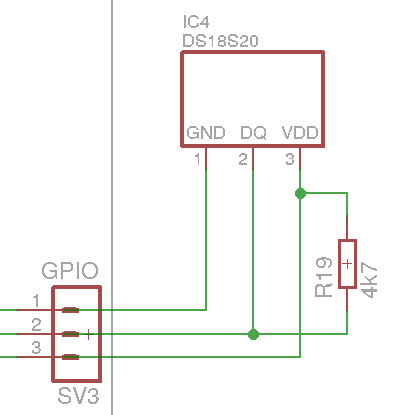
- GPIO A - Vdd (GA=2)
- GPIO B - Temp sensor (GB=7)
Nodo shop board
Ever since revision 2.7, the Nodo shop boards include a pull-up resistor that can be connected to GPIO B by shorting solder jumper JP3.Out of the box, these boards also come with the GPIO pins connected to LEDs E & F. To use the GPIO pins for a temperature sensor, the connections to the LEDs must be broken. A sharp knife can be used to cut the PCB traces that short solder jumper JP1 and JP2.
To confirm that the PCB traces are cut correctly, configure both GPIO pins to Ground (GA=1, GB=1). LEDs E & F should not light. Jumper JP3 can be checked by setting GPIO A to ground and GPIO B to Vdd (GA=1, GB=2). Then PR=I should show "PR: I=01". Next change GPIO B to input (GB=0). PR=I should then report "PR: I=00". Finally change GPIO A to Vdd (GA=2) and run PR=I again. That should now report "PR: I=11".
If all the tests produce the expected results, you can power down the OTGW, connect the sensor, power up the OTGW and configure the GPIO B function to Temp sensor (GB=7).